Choosing an antenna for your IoT project is never easy. Yet it is the antenna that will make your product communicate. So how do you choose among the thousands of references that exist? Moreover, how to choose between the
Choosing an antenna for your IoT project is never easy. Yet it is the antenna that will make your product communicate. So how do you choose among the thousands of references that exist? Moreover, how to choose between the
Choosing an antenna for your IoT project is never easy. Yet it is the antenna that will make your product communicate. So how do you choose among the thousands of references that exist?
Moreover, how to choose between the different types of antennas? What are the selection criteria? And finally, how can you be sure that your antenna will perform well? That you have made the best choice on the market?
In this article, we have condensed some advice and we will explain everything to you! A small guide so that you can be in control of your choices. And we have even made a real comparison of the performance of 2 antennas. As if you were there. Get set, let’s go!
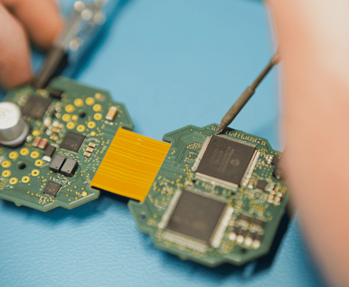
In radio frequency, an antenna is a device that converts an electrical signal into an electromagnetic wave and vice versa. More practically, it is a way of changing from a guided signal (via an electronic track, a wire, etc.) to an unguided signal (which propagates more freely in space).
Antennas are used whenever a product has radio on board: smartphones, satellites, gate remotes, etc. They are essential for a connected object: without them, there is no radio. They directly influence the radio performance of the connected object (range, throughput to a certain extent).
Ceramic, PCB, quarter-wave or half-wave, helical … There are many types of antennas, meeting different needs. The main technologies used in the IoT are the following:
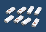
It can be rectilinear or helical, depending on the space and directivity constraints.
There are many other types of antennas, but they are less commonly used in the IoT.
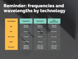
The operating frequency, the size and the directivity are 3 elements that will guide your choice towards YOUR antenna. You will find all the technical information about the antenna in the documentation of your suppliers before proceeding with any type of test.
The main criterion is of course the operating frequency. There are monoband and multiband antennas, the latter being used for example for cellular networks. They are often defined by their application. They are often defined by their application:
A multi-band antenna generally performs with slightly lower quality than a single-band antenna. Experience has shown that a single-band antenna is good when its S11 is less than -10 dB, and a multi-band antenna is good when it is less than -6 dB.
| Precision: S11 is a ratio that helps to determine the reflection of a system, i.e. the power returned. The antenna is supplied with electrical power (e.g. by connecting it to a device), and the power reflected from the antenna is measured. The S11 is the ratio of the reflected power to the sent power, measured on a logarithmic scale. A good antenna will return little power because it will convert this electrical power into electromagnetic power. The more “negative” the S11 is, the better the antenna is on this parameter. |
The size of the antenna depends mainly on its operating frequency. The classic antenna is a dipole the length of wich corresponds to the half-wavelength. There are also “quarter-wave” antennas, which are more compact, but require a ground plane to operate.
The antenna must be adapted to the environment in which it operates. Some antennas require a specific surface to function properly: mounting on a metal or glass wall, glued to plastic, etc. Sometimes the antenna needs to be provided with a ground plane in order to function, as is the case with quarter-wave antennas.
If you want to review an overview of the different communication networks for your IoT project, you can read this article.
The directivity of an antenna defines the distribution of radiation around the antenna. Some antennas are omnidirections, i.e. the signal power is approximately the same in all directions. This is the case with quarter-wave or half-wave antennas, for example.
However, it is sometimes better to opt for a directional antenna, i.e. one where the signal is mainly directed in one direction.
Note that the directionality of an antenna is the same for transmitting and receiving. A directional antenna will better receive a signal from a certain direction. It is used, for example, for DTT reception (Yagi antenna), where the transmitter and receiver are fixed. GNSS antennas also often have a preferred direction, since the satellite signal always comes from the sky.
The directivity of an antenna is defined by its gain, relative to an ideal isotropic antenna. It is given in dBi, isotropic deciBel. In the manufacturer’s documentation, radiation diagrams can be found which allow the directivity of an antenna to be determined.
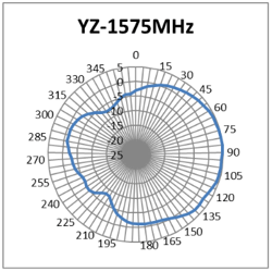
GNSS antenna (Molex 2116240001) directive, 4.5dBi gain in best direction
The standing wave ratio and the reflection coefficient (noted Γ) are two measures that allow the quality of the antenna to be qualified. It defines the signal actually transmitted to the antenna, compared to the signal reflected by the antenna (which will not be radiated). SWR is greater than 1. The closer it is to unity, the less signal will be reflected from the antenna, and therefore the more efficient the antenna will be. In the documentation, one often finds the “Return Loss”, which is proportional to the logarithm of the reflection coefficient. The more negative the return loss is, the better the antenna is adapted to the frequency under consideration.
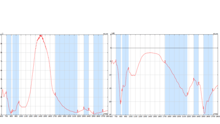
Antenova Moseni, VSWR on the left and Return Loss on the right. The blue areas correspond to the frequencies adapted to the antenna
We also see the efficiency of the antenna, which is the ratio of the actual radiated power to the absorbed power.
As previously discussed, a good antenna must meet two main criteria (for a given frequency):
Therefore we conducted an experiment to compare the performance of two antennas with each other according to their environment.
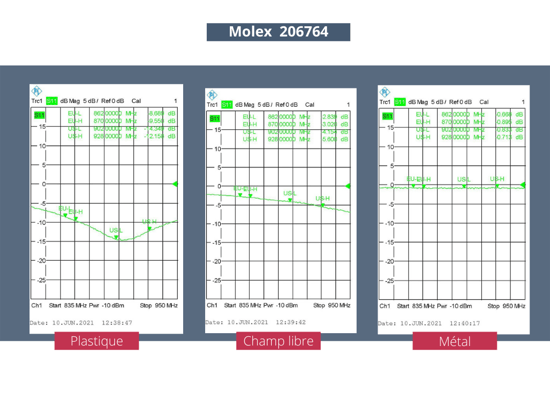
As part of a project with a client, a study had to be carried out to determine which of the 2 antennas would be the most suitable and efficient. We, therefore, conducted our tests on 2 dual-band Molex antennas (868 MHz and 915 MHz).
We have chosen to conduct this experiment by placing the antenna in three different environments: on a metal case, a plastic case and in the open air.
With the help of a vector network analyser (VNA), we will take measurements. This type of device is very expensive. If you do not have one, it is always possible to rent one weekly, or to carry out tests in labs that have this type of device.
In any case, at some point, you will have to call in a laboratory if you want to pass the certifications and your antenna to meet the standards. You can read more about this in this article on EMC and this one on CE certification.
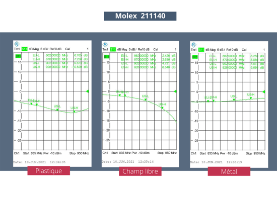
 On the rectangular graphs, we can therefore observe, according to our requirements, that :
We also note that the second antenna has better performance, in the order of 2 to 3 dB. The Molex 211140 is indeed less bulky, but its performance has been reduced at the expense of its compactness.
In order to complete the validation of an antenna, it is also necessary to check the efficiency of the antenna. Thanks to the S11, we have seen that the 2 antennas correctly absorb the electrical power supplied by the source (here the VNA). We must now make sure that this power is correctly converted into an electromagnetic wave, and not lost as heat.
To do this, we will use an RF generator connected to the antenna to be tested, and we will measure the electromagnetic radiation created by the system. A reference antenna is placed a few metres away and the signal received by it is measured.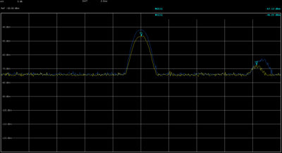
For this test, two antennas, A and B, were successively placed on a turntable and rotated. The measuring device (a spectrum analyser) is configured in “Max Hold”, i.e. it only retains the maximum value measured. The blue curve corresponds to antenna A, and the yellow curve corresponds to antenna B.
There is a difference of several dB between the two received powers. For the same power supplied by the transmitter (and therefore for the same power consumption), antenna A transmits more and therefore has better performance.
En se plaçant en “Max Hold”, on compare le signal maximum des deux antennes. On peut également prendre des mesures successives à intervalle régulier (par exemple, tous les 15°) puis tracer un diagramme de rayonnement. Ce sont ces graphes qui sont souvent présentés dans les documentations techniques.
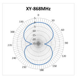
radiation diagram of the Molex 206764
Once these tests have been carried out, it is still possible to modify the parameters of the antenna to optimise its performance. We will not go into detail on this part as it is more complex.
It is important to know that a transmitter/receiver is designed to operate at 50 ohms, but that in reality, the impedance of the antenna will not always be exactly 50 ohms.
So the engineering teams take care to readjust the antenna impedance so that the system performs optimally and can also perform equally well in a slightly different context (because that is what will affect its performance). This practice helps to minimise losses.
You now know the main steps for choosing the antenna for your connected product. Beyond the physical aspect of the antenna (size and compatibility) and the choice of technology, the tests to be carried out will be decisive for the radio performance of your product.
Un peu de lecture
Des articles, des podcasts, des webinars… et surtout des conseils pratiques ! En bref, une collection de ressources pour mener à bien votre projet.